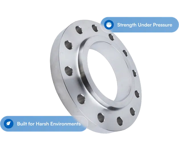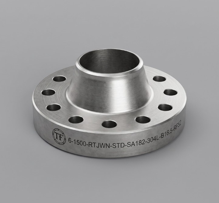
A line that reads "8 inch Class 300 RFWN A105" is a full description which includes the face type of the flange, but not necessarily the face finish. These are technically two different specifications, and only one of them is the surface the gasket actually seals against during installation.
Raised face, flat face, ring type joint, tongue and groove, male and female: that is geometry, the shape machined into the flange. Surface finish is the texture cut into that face, measured as roughness rather than in inches. Although typically machined as an industry standard, a raised face can arrive coarse or near polished, and the two will behave very differently under the same gasket seal. If a joint is weeping and the material, class, gasket and bolt load all check out, the finish is the next place to look for compatibility issues.
Facing Type Is Not Surface Finish
Facing type is what most specs capture, because it is what changes the part number. RF, FF, RTJ, T&G and M&F describe where the gasket sits and what shape it has to be. Our complete guide to raised face flanges covers that geometry, and our breakdown of flange face types walks through the full set.
Surface finish is what happens on the lathe after the geometry is decided. It is the texture of the sealing surface, specified as a roughness average, or Ra, in microinches or micrometers. You will also see it written as AARH (Arithmetic Average Roughness Height) on mill certs and comparator plates, which is the same concept. Most purchase orders name the facing and stop, which is why the finish tends to be whatever the shop runs by default. That is usually fine, but you really need to define it for your own application to be sure.
What ASME B16.5 Actually Requires
The standard does not leave the finish open to interpretation. In the current edition, ASME B16.5-2025, paragraph 6.4.5 sets it in three parts, and defines them in two sentences that matter more than any of them.
Raised face and flat face, which the standard files under "other flange facings," get either a serrated concentric or serrated spiral finish, with a resultant average roughness of 125 to 250 microinches Ra (3.2 to 6.3 micrometers). The standard also specifies the cut: 45 to 55 grooves per inch (1.8 to 2.2 grooves per millimeter), from a cutting tool with an approximate 0.06 inch (1.5 mm) radius or larger. For a flat face, that finish has to run the full width of the gasket seating surface.
That is tighter than the "125 to 500 microinch, 30 to 55 grooves per inch" figure you will find on half the piping sites. That figure is not technically within B16.5 code, but rather found in other specifications. It is a gasket manufacturer's installation recommendation crossed with a legacy shop description, and 125 to 500 also happens to be what the European standard allows, which is how the two get tangled on projects running both.
Tongue and groove, and small male and female, get a smoother seat: the gasket contact surface shall not exceed 125 microinches Ra (3.2 micrometers).
Ring type joint grooves get smoother still: the side wall of the groove shall not exceed 63 microinches Ra (1.6 micrometers), because a solid metal ring seals on a line and has no tolerance for tool marks. Groove dimensions live on our RTJ face dimensions and flange tolerances page, and our RTJ flange guide covers where the metal seal earns its keep.
Then the sentence that runs the whole show: other finishes may be furnished by agreement between the user and the manufacturer. Anything outside those bands is available. It just has to be written down. The flange does not know what gasket is coming.
Two more things the standard leaves up to you: Concentric or spiral is the shop's choice unless you specify one, with 99% of cases being a spiral finish due to machine time and labor costs. And for NPS 26 and larger you are under ASME B16.47, not B16.5, so confirm the requirement against whichever standard your flange is actually built to.
A note on the finish names
Look for "stock finish," "smooth finish," "phonographic" or "cold water finish" in ASME B16.5 and you will not find them. None of those terms appear anywhere in the standard. They are shop and catalog language, useful shorthand between people who already agree on what they mean, and worth nothing on a purchase order that has to be enforceable. B16.5 describes one serrated finish and one roughness band, and lets everything else through by agreement. So if a drawing says "smooth finish," that is a conversation, not a spec. Ask for the Ra number.
Concentric or spiral is a real choice. A concentric serrated finish is a series of closed rings, so no single groove runs from the bore to the outside diameter. A spiral serrated finish is one continuous groove doing exactly that. Both are permitted and both seal, and for most service it makes no practical difference. Some owner specs call out concentric on gas and light hydrocarbon service anyway, reasoning that a closed ring does not machine a continuous path across the seal. That is a spec-writer's convention rather than a code requirement, so if your project wants it, it belongs on the purchase order. Almost all cases will default to spiral finish unless otherwise requested for pricing.
Where EN 1092-1 Differs
If you are working to European standards, EN 1092-1 covers the same ground with different numbers. Its 2013 edition sets facing types A, B1, E and F at Ra 3.2 to 12.5 micrometers, and types B2, C, D, G and H at Ra 0.8 to 3.2 micrometers.
Read that against ASME and the gap jumps out. Type B1 is the standard European raised face, and it permits a face up to twice as coarse as ASME allows on the equivalent joint. On a project mixing ASME and EN components, the finish is one more line worth confirming rather than assuming, especially if one gasket spec is covering both sides of the plant.
Matching the Finish to the Gasket
The finish is not a quality grade where smoother is better. It is a match to the gasket, and the mismatch is bad in both directions.
Gasket family | Ra (microinch) | Ra (micrometer) | Note |
Soft sheet and graphite | 125 to 500 | 3.2 to 12.5 | Tolerates the coarse end. Anything past 250 is outside the B16.5 band and has to be specified |
PTFE and expanded PTFE sheet | 125 to 250 | 3.2 to 6.3 | Conformable but thin. Check the product sheet, several ePTFE products have their own range |
Spiral wound and kammprofile | 125 to 250 | 3.2 to 6.3 | The B16.5 serrated band, as designed |
Metal jacketed, soft filler | 63 to 125 | 1.6 to 3.2 | Sources vary between 63 to 80 and 64 to 125. Ask the gasket maker |
Solid metal and corrugated | 63 or better | 1.6 or better | Seals by line or area contact |
RTJ groove side wall | 63 max | 1.6 max | Required by B16.5, not optional |
Read that as the gasket driving the finish, not the other way around. If the gasket is bought and the flanges are still open, the gasket dictates what you ask for. If the flanges are already in the rack, the finish limits what gasket you can sensibly seat on them. And for the joint in front of you, the gasket manufacturer's published recommendation governs, not a table on a supplier's blog.
What the Wrong Finish Does
Too smooth for a soft gasket and there is nothing for the gasket to key into. You are relying on friction alone, and under load and thermal cycling a compressed sheet or PTFE gasket creeps outward, tightness drops, and a slow leak shows up weeks after commissioning. This is the failure people misdiagnose most often, because the flange looks immaculate and the bolting gets blamed.
Too rough for a hard or thin gasket and the gasket cannot conform into the grooves. Spiral wound windings and solid metal seals do not have the compressibility to fill a 500 microinch profile, so the peaks hold the gasket off and the valleys become leak paths straight across the face. A thin PTFE sheet on a coarse face fails the same way.
Serrations that are shallow or wrongly spaced are the quiet one. A worn tool or a bad feed can produce a face that measures inside the Ra band and still seals poorly. That is exactly why B16.5 specifies groove pitch and tool radius and not just roughness.
Then there is the face that has been dressed in the field with a grinder. That is not a finish. It is a random surface with no defined roughness and usually a few radial scratches, and it will not seal reliably against anything.
How to Check It Before It Goes in the Line
Here is the part most people get backwards, and the standard is unusually blunt about it. ASME B16.5 says the finish of the gasket contact faces shall be judged by visual comparison with Ra standards, referencing ASME B46.1, and not by instruments having stylus tracers and electronic amplification.
Read that again if you own a profilometer. For a conformance call under B16.5, the stylus instrument is not the method. The method is a surface finish comparator: a small set of reference specimens at known roughness values that you hold against the face and compare by eye and fingernail. It takes about five seconds, it is the check almost nobody performs in receiving, and it is the check the standard actually asks for. A profilometer still has its uses in a lab or a failure investigation. It is not what decides whether the flange meets the spec.
What Counts as Damage
B16.5 does not leave this to judgment either. Paragraph 6.4.6 sets acceptance limits for imperfections in the facing finish, with dimensions tabulated by size, and two rules worth memorizing:
Imperfections less than half the depth of the serrations are not cause for rejection. Shallow marks that do not break the groove profile are cosmetic.
Protrusions above the serrations are not permitted. A raised burr is rejectable at any size. A dent and a bump are not the same problem.
Adjacent imperfections have to be separated by at least four times the maximum radial projection, and radial projection is measured from the centerline of the bore, not eyeballed across the face.
The dimensional limits for raised face and large male and female, in U.S. customary units, run roughly like this:
NPS | Max radial projection, no deeper than the serrations | Max radial projection, deeper than the serrations | Max depth, deeper than the serrations |
1/2 through 2-1/2 | 0.12 in. | 0.06 in. | 0.06 in. |
3 | 0.18 in. | 0.06 in. | 0.06 in. |
3-1/2 through 6 | 0.25 in. | 0.12 in. | 0.12 in. |
8 through 14 | 0.31 in. | 0.18 in. | 0.18 in. |
16 | 0.38 in. | 0.18 in. | 0.18 in. |
18 through 24 | 0.50 in. | 0.25 in. | 0.25 in. |
Work to the current edition of the standard for the full table and the SI values. And note what the table does not cover: ring joint grooves and small male and female have their own requirements.
Visually, the thing to hunt for is still a radial scratch. Any mark running from the bore toward the outside diameter is a potential leak path, and a radial gouge deeper than the serrations is a rejection or a reface, not a reason to reach for a longer breaker bar.
On that last point, bolt-up is its own discipline. ASME PCC-1 is the governing standard for flanged joint assembly, and no assembly procedure recovers a joint where the finish and the gasket were mismatched from the start. For torque values and seating stress, go to your bolting or gasket manufacturer. We will tell you what the flange is; they will tell you how to tighten it.
Damage, Refacing and When to Stop
Refacing a flange is normal maintenance, and a portable facing machine can restore a proper serrated finish in place. Obviously what it cannot do is add metal back, despite the fact that weld repair is permitted in some cases on the body of the flange itself (and not recommended on the facing).
That matters more than people expect, because there is not much height to work with. B16.5 puts the raised face at 0.06 inch on Classes 150 and 300, and 0.25 inch on Classes 400 through 2500, each measured on top of the minimum flange thickness. On a Class 150 flange, the entire raised face is a sixteenth of an inch. A few passes and the geometry stops conforming. Track it against the dimensional tolerances in the standard, and let the equipment manufacturer's procedure govern the cut.
Ring type joint grooves are a separate discipline. The sealing happens on the groove flanks rather than on the flat face, and the groove has its own dimensional and finish requirements. A worn or corroded RTJ groove is a remachining job with a proper groove tool, not something to dress by hand.
The Bottom Line
Facing type gets specified. Surface finish gets inherited but should also be specified by the end user. Most of the time the B16.5 serrated finish is exactly right and nobody has to think about it. The exceptions are the joints that matter: soft gaskets that want a coarser face than the standard gives them, metal seals that want a smoother one, tongue and groove and RTJ where the standard already has an opinion, European components sitting in an ASME line, and any flange that has been in service long enough to have been dressed by somebody in a hurry.
It costs nothing to name the finish on the purchase order and five seconds to check it in receiving. It costs considerably more to find out at hydrotest.
If you have a gasket already selected and want the flange finish specified to match it, or you are working a project that mixes ASME and EN components and want the roughness requirements reconciled before anything ships, send us the details. We will get you flanges with the right facing, the right finish, and the certs to document both.
Texas Flange | 281-484-8325 | texasflange.com